The Main Systems Design
By Dermot Tynan, almost 13 years ago.
In terms of the system architecture, we're planning on using two separate computer control planes to manage and steer the boat from start to finish.
At the lowest level, a custom Atmel (ATmega8) board will act as a basic "autohelm", driving the boat to a specific True Wind Angle or TWA. As the breeze shifts, so too will the boat, to maintain that TWA. This is a basic PID algorithm for controlling the rudder and mainsail in relation to the specified TWA and is very similar in design and implementation to your average sailboat autohelm.
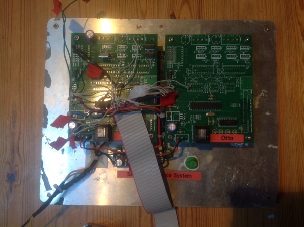
Igor and Otto
By Dermot Tynan, almost 13 years ago.
The Kalopa motor control board was designed as a general-purpose Atmel board with ancillary electronics for a wide variety of purposes. It includes two H-Bridge motor controllers, driven by two 16 bit PWM outputs. You can exchange one of the motor controllers for an 8-channel servo controller, also using one of the PWM outputs. It has a standard RS232 port with an RJ45 connector on the end. There is a MAX232 to convert logic levels to proper RS232 voltages. If you want to use radio control, you can instead populate the board with an R5-434 radio receiver. It will listen for data on 434MHz and feed it to the Atmel. The processor itself is the bog-standard Atmel ATmega8 with 8k of code and about 512 bytes of RAM.
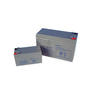
Battery and Solar Design
By Dermot Tynan, over 12 years ago.
There will be at least two Vcc busses on board. Labeled, oddly enough, as Vcc1 and Vcc2. The difference between them is that Vcc1 is always on, at all times, and Vcc2 (through VccN) are selectable by Igor.
The main processor runs off Vcc2, but Igor (and Otto) both run off Vcc1. In situations where voltage levels are critical, Vcc2 will be switched off and the boat will continue on whatever course had previously been set, until either voltage levels are healthy, the specified "wake-up" time has elapsed, or there are critical issues which require Mother to get involved. A critical situation could be something like a dramatic wind shift, or an error such as a mis-reading from a sensor.

The Software...
By Dermot Tynan, over 12 years ago.
I've been asked recently, about the software platforms used on board Beoga Beag. This seems as good a time as any, to talk about the various layers. As mentioned previously, the lower layer is a custom board, running an ATmega8 Atmel processor. The software (Igor and Otto) is custom-written in C for the boat.
I love it when a Plan comes together...
By Dermot Tynan, over 12 years ago.
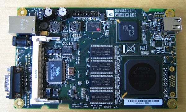
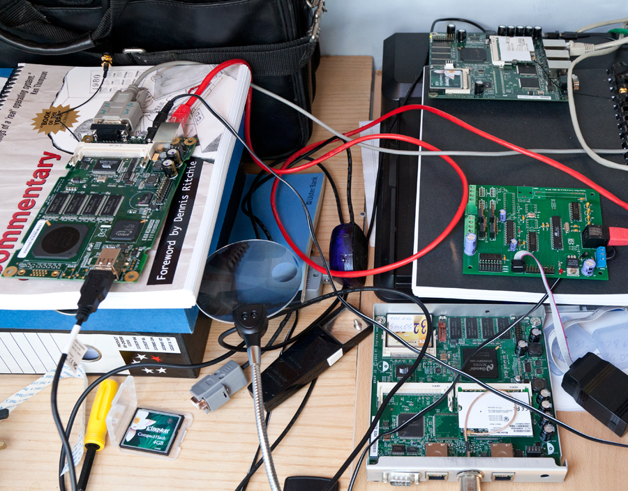
The new ALIX board has arrived. It's to the left of the picture, sitting on top of a copy of the Lyon's Notes (which is appropriate). It's running my custom version of NanoBSD quite nicely, and can see the GPS without any difficulty. The GPS unit is a BU-353 unit (the USB version) which is out of the shot. It's attached to the window, and gazing at the man-made stars. To give a breakdown of what's in that photograph, the ALIX is on the left. In the USB port is the GPS, the RS-232 cable at the top of the board is communicating with my development machine (running FreeBSD). The red CAT5 cable is connecting the board to the "house network." The Atheros CM9 radio is a miniPCI card mounted on the underside of the board. It works on 5.8GHz and on 2.4GHz. In this case, I'm using 5.8GHz because (apparently) it has better cross-water characteristics and the band isn't as crowded. The mini coax cable is at the top-left of the picture, connected to a short, 9dBi antenna. You can also see a 12v cable with barrel plug. At the top-right of the picture is a WRAP board, also developed by PC Engines. It was being used as a testbed for the operating system, but that is no longer needed thanks to the ALIX.
Upcoming Missions
- Galway Bay Loop, Waiting for Vessel Availability
Search
Recent Posts
- May 2023 (1 post)
- April 2023 (1 post)
- March 2023 (1 post)
- February 2023 (2 posts)
- March 2022 (3 posts)
- March 2021 (1 post)
- August 2020 (1 post)
- May 2019 (1 post)
- April 2018 (1 post)
- November 2017 (1 post)
- April 2017 (1 post)
- November 2016 (1 post)
- September 2016 (1 post)
- August 2016 (1 post)
- January 2014 (2 posts)
- October 2013 (7 posts)
- September 2013 (1 post)
- August 2013 (3 posts)
- June 2013 (3 posts)
- May 2013 (4 posts)
- April 2013 (3 posts)
- March 2013 (9 posts)
- February 2013 (8 posts)