I love it when a Plan comes together...
by Dermot Tynan in Microtransat
Posted on Thursday, May 16, 2013 at 08:00
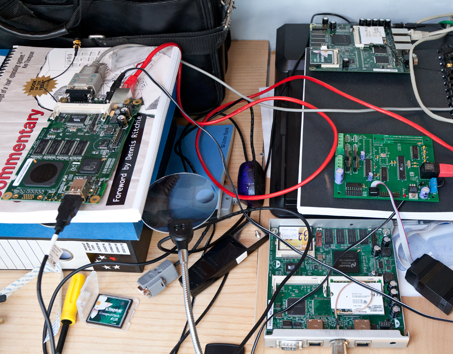
The new ALIX board has arrived. It's to the left of the picture, sitting on top of a copy of the Lyon's Notes (which is appropriate). It's running my custom version of NanoBSD quite nicely, and can see the GPS without any difficulty. The GPS unit is a BU-353 unit (the USB version) which is out of the shot. It's attached to the window, and gazing at the man-made stars. To give a breakdown of what's in that photograph, the ALIX is on the left. In the USB port is the GPS, the RS-232 cable at the top of the board is communicating with my development machine (running FreeBSD). The red CAT5 cable is connecting the board to the "house network." The Atheros CM9 radio is a miniPCI card mounted on the underside of the board. It works on 5.8GHz and on 2.4GHz. In this case, I'm using 5.8GHz because (apparently) it has better cross-water characteristics and the band isn't as crowded. The mini coax cable is at the top-left of the picture, connected to a short, 9dBi antenna. You can also see a 12v cable with barrel plug. At the top-right of the picture is a WRAP board, also developed by PC Engines. It was being used as a testbed for the operating system, but that is no longer needed thanks to the ALIX.
In the middle of the right of the image is a prototype motor control board of my own design, with an Atmel ATmega8. The RJ45 connector is actually a serial cable, even though it looks like it is connected to the other end of that CAT5 cable. Connected to it is a USB programmer made by Lady Ada. If you work with Atmel chips, you need one of these puppies!
On the bottom right is another WRAP board. This one is used for "ship to shore" communications. Very shortly, I'll start building the actual Atmel boards (Otto and Igor) which will steer the boat and manage the environmental systems. In case you're wondering, Otto is short for "Otto Von Helm" (autohelm) and Igor is aptly named after that staple of Frankenstein movies; "More Power, Igor!!"
The hull outer fibreglass coat is completed, and I hope to do the interior layers in the next week or so. After that, it's down to sanding and epoxy coating and the hull can be moved up to the development lab. I still need to seal some of the compartments with PU foam, and of course attach the keel, but it will be great to see the hull kitted out with some of the electronics, if only as a fit-out test.
The SLA battery has arrived, and will be charged up for a few days. The first mission for the battery will be to discharge itself through a heavy duty resistor bank, at around 500mA. As it's an 8Ah battery, that's a C/16 discharge rate which should be fine. I won't fully discharge it more than once or twice, as I take voltage and current measurements as the battery discharges. The plan is to plot the voltage readings (at full current draw) as the battery discharges so that I can determine in the Igor software, what percentage of charge is still left. To simulate the charge cycle, I will add a charging circuit on a timer, and drive a charge onto the battery for about 8 to 10 hours a day. I'll pull around 250mA continuously, and measure the battery cycle. I will probably need to pump in around 600mA during the charging cycle, plus the 250mA for the load. That should be a more typical example of how the battery will operate. Trying to decide the battery charge voltage so that it doesn't overcharge, doesn't charge too quickly, but gets a decent charge during the hours that the solar panels are delivering juice, isn't trivial. It is complicated by the change in battery temperature, which reduces the float voltage.
But the important thing right now is the wind direction indicator. I need to get back to that particular design...
Search
Upcoming Missions
- Galway Bay Loop, Waiting for Vessel Availability
Recent Posts
- May 2023 (1 post)
- April 2023 (1 post)
- March 2023 (1 post)
- February 2023 (2 posts)
- March 2022 (3 posts)
- March 2021 (1 post)
- August 2020 (1 post)
- May 2019 (1 post)
- April 2018 (1 post)
- November 2017 (1 post)
- April 2017 (1 post)
- November 2016 (1 post)
- September 2016 (1 post)
- August 2016 (1 post)
- January 2014 (2 posts)
- October 2013 (7 posts)
- September 2013 (1 post)
- August 2013 (3 posts)
- June 2013 (3 posts)
- May 2013 (4 posts)
- April 2013 (3 posts)
- March 2013 (9 posts)
- February 2013 (8 posts)
