Hull 002
by Dermot Tynan in Microtransat
Posted on Saturday, September 24, 2016 at 10:55
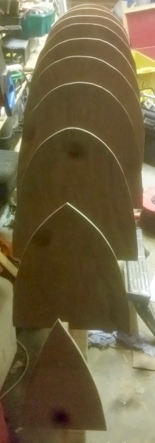
I have discussed the hull construction process in earlier posts, which you can find via the above search bar. To recap, you take the hull design and "loft" the shape of each section or bulkhead, from the drawing. You then cut this out of 6mm marine ply (or equivalent), mount each of the stations onto a strongback, and now you have something which forms the shape.
I also need to add a keelson to the picture. A keelson is a long, keel-like piece of wood which runs from stem to stern, connecting the bulkheads. I cut one already but it turned out to be too short due to a miscalculation on my part. Generally I cut a thin (about 2cm wide) outline of the keel of the boat, from a sheet of ply.
An example of the keelson can be seen in the image associated with this post: The keel is attached.. It has been clamped in place and is glued (with the wrong glue) to the bulkheads.
You can see from the image at the top of this post that I have almost completed this stage, and the bulkheads are nearly ready for "skinning". In this case, I use very thin balsa wood to cover the hull shape. You can also use thin marine ply. I like balsa wood because it's easier to follow a compound curve (one which curves in two dimensions). I will probably end up using two layers of thin balsa. Again, I could use a thicker balsa wood and only do one layer, but it's hard to find balsa wood which is in at least 2.4m strips. As a result, I will need to connect one sheet to another with a "butt joint". The problem with this is that it creates a sharp corner where the two pieces meet, unless you can either glue another piece inside the balsa wood, or else (in my case) put another layer on top, making sure that the seams don’t align.
You can see an example from Hull #001, here: Hull 001 is almost ready for fibreglass. You can see that the balsa smoothly follows the curvature of the hull. You can also see that there is a butt joint about a third of the way along the starboard side. It is this type of joint which interrupts the nice bending flow of the hull. In that particular case, I grafted a small section of balsa wood behind the joint in the hope it would help the balsa to curve with the hull. It mostly worked.
Once the balsa skin is in place and sanded smooth, I'll cover it with two or three layers of chopped strand matt and polyester resin, inside and out. I will leave every second station in-place, to form bulkheads inside the hull. Unlike the previous hull, I'm not going to seal each compartment. I had originally planned to do this on the basis that if a compartment leaked, it wouldn't sink the boat. I filled all of the unused compartments with closed-cell polyurethane foam. The problem is, while crossing the Atlantic, the day and night temperature extremes can be significant. If the compartments are sealed, then as the temperature rises (as the boat heads South), the air pressure increases until it is forced out of a seam, somewhere. Cool night-time temperatures will result in a partial vacuum in those compartments and they will either cause the structure to collapse or else they may draw in sea water, thus making the situation worse than having compartments which can breathe.
So these ones will vent.
I will also add ducting between the compartments for wiring. One of the problems with the first hull is it’s very difficult to retroactively change any of the wiring or circuitry. The wiring harnesses have all been embedded into the structure.
Anyway, the hull is almost looking like a boat. Another few weekends will get it to the point where it is sealed and seaworthy. Meanwhile, I am working on the software (again) and some of the algorithms.
Search
Upcoming Missions
- Galway Bay Loop, Waiting for Vessel Availability
Recent Posts
- May 2023 (1 post)
- April 2023 (1 post)
- March 2023 (1 post)
- February 2023 (2 posts)
- March 2022 (3 posts)
- March 2021 (1 post)
- August 2020 (1 post)
- May 2019 (1 post)
- April 2018 (1 post)
- November 2017 (1 post)
- April 2017 (1 post)
- November 2016 (1 post)
- September 2016 (1 post)
- August 2016 (1 post)
- January 2014 (2 posts)
- October 2013 (7 posts)
- September 2013 (1 post)
- August 2013 (3 posts)
- June 2013 (3 posts)
- May 2013 (4 posts)
- April 2013 (3 posts)
- March 2013 (9 posts)
- February 2013 (8 posts)
