
I originally planned to build a lot of the electrical systems inside the hull, and mount the control electronics on a platform which would connect to the various systems. I quickly learnt that this wasn't going to survive contact with the Real World. I needed something more modular, something more watertight.
The prototype boat had three terminal strips mounted inside the hull. One was for Vbatt, one was for Vcc and one was for Ground. Each solar panel had its own float voltage converter, which took the raw Vsolar power and brought it down to 13.7 volts. Another DC/DC converter converted this float voltage down to 5 volts for the main circuitry. The sealed-lead-acid battery was connected directly to the Vbatt bus. While the internal compartment of the boat was designed to be water-tight, it wasn't to IP65 standards.
So then the division of functions was that the complex printed circuit boards were on a removable plate but the electrical distribution and power conditioning was all inside the hull. I had planned to add a second level of water-tight enclosure around the delicate circuit boards, but all three power strips ended up with extensive corrosion. So much so that I doubt any voltages would have passed between the wire connectors and the terminal strips. Back to the drawing board!
The revised architecture uses IP65 cases like the one shown above. The base box is mounted in the hull, with the smallest number of components permanently installed. Ideally only the interconnecting wires would remain in the hull. Every core component would have its own case. Within the case, the electronics is installed using a layered system.
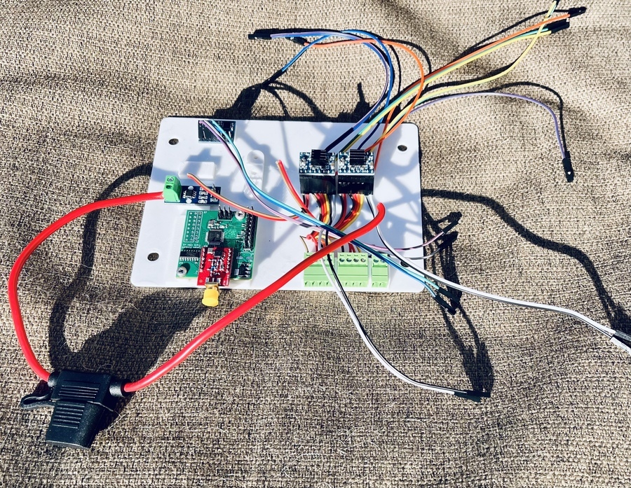
The image above shows some of the electronic boards mounted on a 3D-printed “sled”. On the bottom-left is the AVR-based controller. Also shown are two stepper-motor controllers and some signal conditioning.
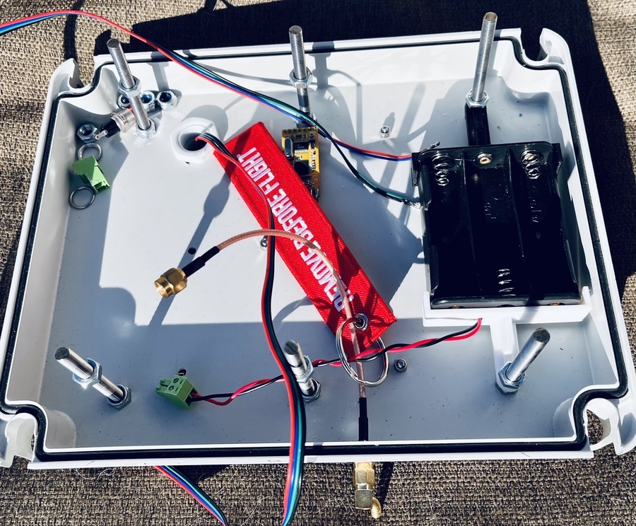
This image shows the inside lid minus the aforementioned sled. The sled is mounted on threaded rods mounted in the lid. On the right is the carrier for three 18650 batteries. In this configuration the batteries cannot be charged in-situ.
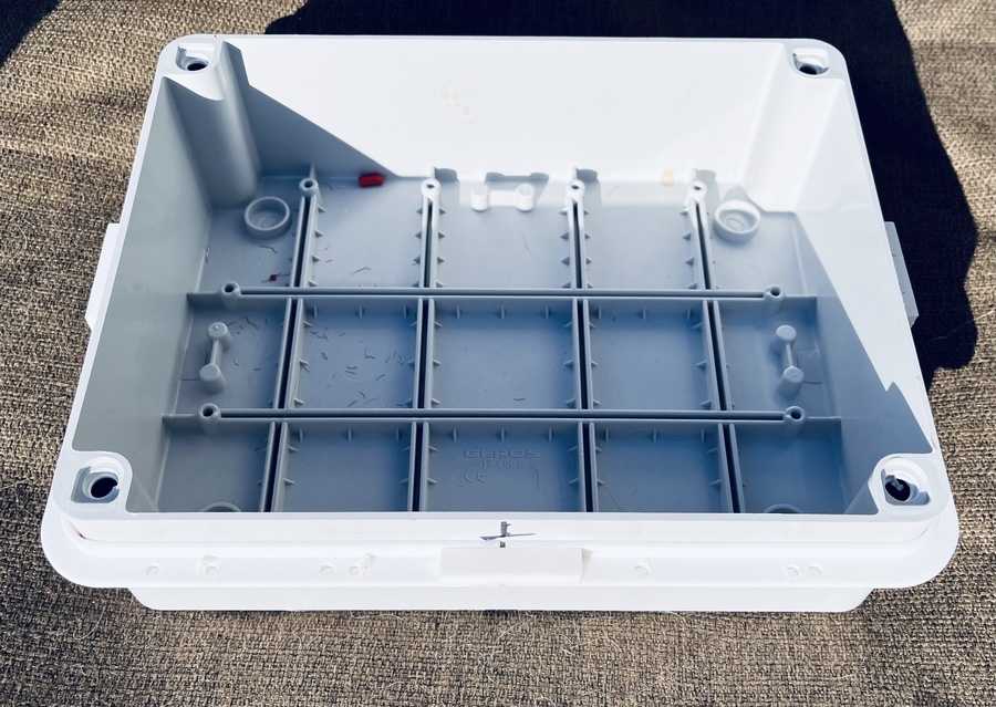
This picture shows the case shell which is mounted into the hull. Cabling such as stepper motor coils or zero-switches will enter through the base of the case in a watertight configuration.
The advantages of a system like this are numerous. Firstly, and most obviously, it is much easier to maintain a completely watertight seal. But also, by making the system more modular, testing is greatly improved. I have been slowed down quite a bit during the course of the pandemic, by access to the hull itself. By being able to separate out as much of the electronics into a portable "box" for testing and development, means that I am no longer constrained. I can even build a test harness with a rudder servo or stepper motor, and a main sail servo or stepper. I can then simulate the effects of the system over time, without the need for an actual hull. I can also do more destructive testing of the hull to see how it performs under more adverse conditions.
If you look at the sled image above, you can see that it is possible to enclose all of the key systems in quite a small board.